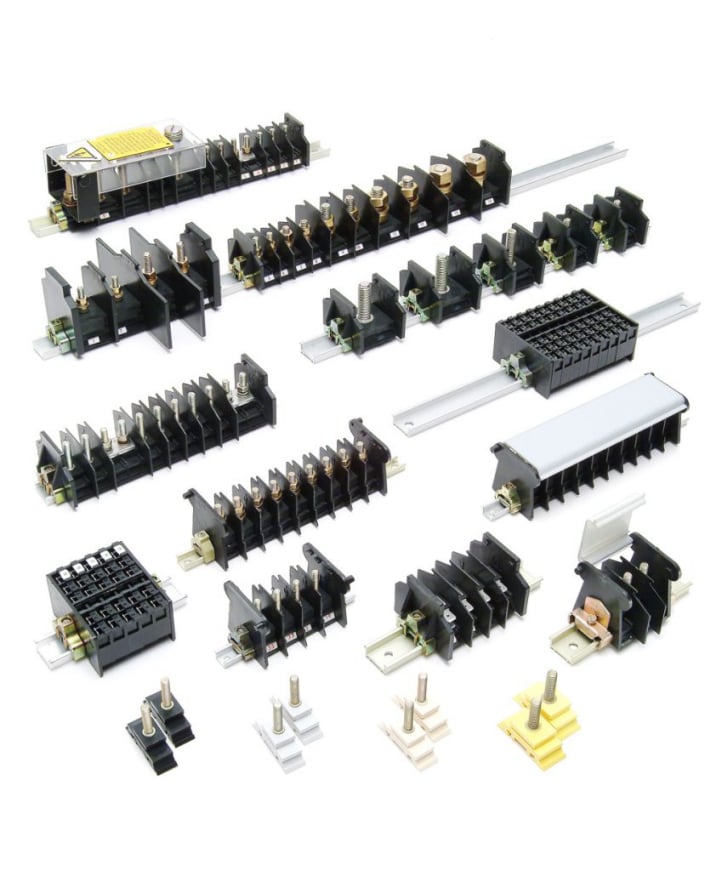
Terminal Rails: Creating Structured and Maintainable Electrical Installations
Modern electrical control systems depend on organisation as much as they do on individual components. Inside control cabinets, switchgear, machinery and distribution equipment, conductors need to be terminated securely and arranged in a way that allows engineers to understand, inspect and maintain the system efficiently. A poorly organised panel can make even simple maintenance tasks unnecessarily difficult.
Terminal rails provide a convenient and standardised way to mount terminal blocks and other compatible electrical devices within an enclosure. By creating a fixed mounting platform, they allow components to be positioned in an orderly sequence rather than installed individually in different locations. This helps create clearer wiring routes and makes individual circuits easier to identify.
The rail itself may appear to be a relatively basic component, but it forms the structural foundation for a large proportion of the terminal arrangement within many industrial control panels.
Terminal blocks can be mounted side by side along the rail, creating defined groups for different circuits. These may include incoming supplies, outgoing loads, control signals, sensors, actuators and protective conductors.
By grouping terminals logically, engineers can make the finished installation easier to understand.
For example, terminals associated with one piece of machinery can be positioned together, while power and control wiring can be separated into clearly identified sections. This can reduce confusion during installation and later fault finding.
Why Terminal Rail Layout Matters
The physical arrangement of a terminal assembly affects both initial installation and future maintenance.
A terminal block located in an easily accessible position can be wired, tested and replaced relatively quickly. The same component positioned behind other equipment or too close to cable ducting may be considerably harder to work with.
Designers therefore need to consider access as well as component density.
Electrical panels are often designed to fit as much equipment as possible into a limited enclosure. While efficient use of space is important, overfilling a terminal rail can make maintenance difficult and leave no room for later expansion.
Providing some spare rail capacity can be useful where equipment may be modified in the future.
Industrial machinery frequently changes during its working life. New sensors may be added, additional control circuits installed or existing equipment upgraded. Spare mounting space can make these modifications considerably easier.
Rail position should also work with cable management.
Cable ducts are commonly installed above or below terminal rows. Conductors can be routed through these ducts before being brought out at the appropriate terminal position.
Enough clearance should remain between the duct and the terminals to allow wires to bend naturally and give engineers access to the connection mechanism.
Component identification is another major benefit of a structured rail arrangement.
Terminal markers can correspond with wiring diagrams and electrical schematics. A technician looking for terminal X17, for example, should be able to locate it quickly within the panel.
This becomes increasingly important as system complexity increases.
In a small enclosure containing only a few connections, tracing a conductor manually may be manageable. In a large automation panel containing hundreds of terminals, clear identification can save substantial time.
Rail Profiles, Materials and Accessories
The most suitable terminal rails depend on the components being mounted and the operating environment.
DIN rail formats are widely used because they provide standardised profiles compatible with many electrical components. One of the most familiar is the 35mm top-hat profile, although other formats are used for particular applications.
Compatibility should always be checked against the terminal blocks and devices being installed.
The rail material can also influence performance.
Metal rails are commonly used because they provide good mechanical strength and support for multiple components. Surface finishes can help provide corrosion resistance in environments where moisture or contaminants may be present.
More challenging industrial environments may require additional consideration.
Electrical equipment installed within manufacturing plants, transportation systems, outdoor enclosures or processing facilities can experience vibration, humidity, dust and temperature changes.
The mounting system should therefore be suitable for those conditions.
Secure rail fixing is essential. Long sections carrying many terminal blocks need adequate support so that they do not flex or move while conductors are being connected.
Fixing points should be positioned appropriately along the rail and attached securely to the enclosure backplate or supporting structure.
Accessories can make the terminal assembly considerably more functional.
End stops are commonly positioned at the ends of terminal groups to prevent unwanted movement. Separators can visually or electrically divide different circuit sections, while identification strips and markers improve documentation.
Some terminal systems also include jumper or bridging accessories that allow electrical connections to be distributed between adjacent terminals.
This can reduce the need for additional individual conductors where several terminals require the same potential.
However, bridging arrangements should always be designed and installed according to the requirements of the circuit and the terminal manufacturer.
Protective conductor terminals can also form part of a rail assembly.
Certain systems are specifically designed to make an electrical connection through the terminal to the mounting rail. In these cases, the rail and its bonding arrangement can become part of the protective earthing system.
This makes correct installation particularly important.
The electrical continuity of the complete arrangement must be appropriate for its intended function rather than simply assumed because the rail is metallic.
Terminal technology itself varies considerably.
Traditional screw terminals remain widely used, while spring-cage and push-in terminals can provide different installation characteristics. Each method has its own requirements regarding conductor preparation, access and maintenance.
The choice may be influenced by installation speed, vibration resistance, conductor type and company standards.
Multi-level terminals provide another option where panel space is restricted. These units allow several connection points to be arranged vertically within approximately the same rail width as a conventional terminal.
This can significantly increase connection density.
Careful marking becomes even more important in these installations because several circuits may occupy a relatively small area.
Special-purpose terminals can also be incorporated into a rail assembly.
Disconnect terminals allow parts of a circuit to be isolated for testing. Fused terminals can provide local protection, while test terminals may allow measurements to be taken more conveniently.
The terminal rail can therefore support much more than simple point-to-point connections.
In complex control systems, it can form a structured interface between field wiring and internal panel equipment.
This separation is useful during commissioning and troubleshooting.
Field cables entering the enclosure can terminate at a clearly defined terminal section before internal wiring continues towards programmable controllers, relays, drives or other devices.
Technicians can then test circuits at the interface without necessarily disturbing internal panel wiring.
Standardisation can provide further benefits where businesses manufacture or maintain multiple machines.
Using consistent rail types, terminal families and numbering systems across different panels can make training and maintenance easier.
Engineers become familiar with the layout conventions, while spare parts inventories can potentially be simplified.
Documentation should be updated whenever the terminal arrangement changes.
Adding terminals physically without updating drawings can create problems later when another engineer attempts to trace a circuit.
Good panel design therefore combines the physical terminal arrangement with accurate schematics, terminal schedules and identification.
Inspection should also form part of ongoing maintenance.
Terminal assemblies can be checked for signs of damage, contamination, overheating or loose components during scheduled servicing. The accessibility provided by a properly designed rail system makes these checks easier.
Where modifications are made, installers should ensure that end stops remain correctly positioned and that added components are compatible with the existing rail and surrounding equipment.
Ultimately, terminal rails provide the framework that allows many electrical connections to be organised into a clear, modular and maintainable system. Correct rail selection, sensible positioning, adequate spacing and effective identification can improve installation efficiency while making later inspection and troubleshooting much easier. Although simple in construction, terminal rails play an important role in producing professional electrical panels that can remain accessible and reliable throughout their operating life.